|
|
|
Before doing any toolpath optimization, manually or automatically, before computing the initial toolpath in general, it is essential to have the project well prepared. Resources must be set up correctly, as well as the project settings and the default values of the programming attributes. Things to keep in focus are:
|
|
|
Axes of machine, robot and / or external resource
|
|

|
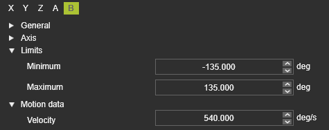
Make sure that the axis limits of the resource are specified correctly to correspond with the real physical device. Obviously this applies to all the axes of any involved resource in the project.
 
|
|

|
The same applies to the maximum speed value (Velocity) of the axes.

|
|
|
Collision group definition and analysis
|
|

|
|

|
Define the collision groups in such a way that there will not be a permanent collision between groups. An optimized solution will never be found in that case.
|
|

|
Exclude unnecessary geometry form the collision groups. This will speed up the process and thus the computation time of automatic toolpath optimization.
For example this can be the front tip of a cutting laser head or the welding wire of the arc weld gun:
But also for example to exclude the robot (wrist) axis on which a tool has been mounted, when the tool has to be analyzed against that robot:

|
|

|
Verify the group pairing of what objects are being analyzed against each other. This is done in the Simulation settings.

|
|
|

|
Verify to not have any hidden collisions anywhere in the scenario during simulation. The toolpath optimization will return with a possibly unexpected, non-visible collision occurrence.
|
|
|
Programming parameters
|
|

|
|

|
Set the programming parameters to match with the ideal process situation. Depending on the applied technology or equipment, things to pay attention to are for example:
•The tool alignment
•The process angles.


|
|

|
Define clear starting positions for the machine or robot, as well as for external axes (resources):
•External axes with explicitly defined values at least at the very first toolpath element in the program.
•A PTP motion to the very first position in the operation.
•Approach and retract positions to be defined with the motion type "Approach" and "Retract".

|
|
|

|
Define proper speed values at the toolpath positions. Process positions should not have zero (=0) speed.

|
|
|
|
Toolpath quality definition
|
|

|
|
This step is recommended at this stage but not mandatory. Because the quality evaluation is executed dynamically at any time, the quality definition therefore can also be set or adjusted at later time.
|
|
The definitions and parameters can be found in the Toolpath quality tech tab on the Programming defaults dashboard or Active program dashboard.
|
|

|
|

|
|
When needed, modify the threshold values of the required attribute, e.g. the maximum allowed process angle deviation.
|
|

|
Activate the target criteria that are relevant for the toolpath quality. Normally, the system defaults should work fine initially for most common scenarios.
For arc welding: the Tool angle deviation angle criteria can be deactivated if the initial tool angle can be oriented freely without any impact on the welding quality.
|
|
|

|
Set the target criteria threshold values to match the specific project or user requirements:
•Usually the angle deviation maximum values (red „no go“ threshold) will be adjusted.
•Axis speed „no go“ values (where available) should be kept to 100% in most cases. This will ensure that the TCP speed on process sections is not being reduced due to too strong axis motions.
Start of no-go area
|

|
What value must never be exceeded?
|
Start of critical area
|

|
Which value should not be exceeded if possible?
|
Start of valuation
|

|
Up to what value does the ideal (green) range extend?
From which value is the status still okay, but no longer ideal?
|
|
|
|
|
|
|
|
Compute the toolpath
|
|
After completing the above mentioned preparation steps, generate the toolpath with the available functionality. Include an auxiliary start operation and end operation to complete the program so far.
|
|

|
|
|
The result can be validated in 3D and /or in the dashboards.
|
|

|
|
|
Make sure to switch on the corresponding display filters to see the quality evaluation and other toolpath specific information.
|
|

|
|
|
|
|
|
Collision validation
|
|

|
|
Although the Collision validation activation is displayed in the panel of the Evaluation criteria, it cannot be modified there. In the simulation player bar the button has to be pressed to actually activate the collision analysis during the simulation and to display its results in the 3D space and the different dashboards.
|
|

|
|

|
The autonomous programming will always run a collision analysis in the background, regardless if it has been activated for the simulation.
|
|
|