Purpose
|
|
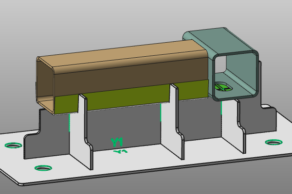
The shape of the support plate that carries, that holds the workpiece is computed directly subtracted from the workpiece shape. This may lead partially, locally to undesired and unwanted solutions.
This page covers the functionality to enhance the workpiece in such a way to avoid these undesired situations. A simplified example will be used to show the effect.
|
|

|
Load the project Fixture_Training_MaskingSurface.cendoc from the folder of this tutorial library.
|
|
|
|
Steps
|
|
1
|
Remove the superfluous material
|
|
1.1
|

|
Change to the Geometry operation mode. Select the workpiece elements and execute the command Change the show / hide state of the selection to hide the workpiece. Then have a look at the areas of the support plate that are not wanted.
Switch to the Hide workspace and retrieve the hidden workpiece to the regular Show workspace.

|
1.2
|

|
Select the Utilities command.

|
1.3
|

|
Select the front edge on the brown tube of the workpiece to enhance the shape. On that edge, open the pie menu and start the Create masking surface command. Together with the 3D preview, a panel appears with the properties of the masking surface.

|
1.4
|

|
Change the Base length to 40mm and look for that the preview reaches far enough to cover also the hole of the green tube. Accept the definition to compute the masking surface. The support plates are updated and notice that the unwanted material has been removed.

|
|
|
2
|
Create a tolerance to the workpiece
|
|
2.1
|

|
Select the lower edge at the bottom rounding of the brown tube. Start the Create masking surface command on the edge. Set the Base length to 7.5mm, the Flange length to 25mm and the Flange radius to 2mm. Then compute the masking surface and notice the new shape of the flange of the support plate.

|
2.2
|

|
Start the Edit command on the masking surface and change the Flange taper angle value to 5 deg. Have a close look to the effect of the change.

|
2.3
|

|
Create the same tolerance relief at the other side of the tube. In case the preview shows in the wrong direction, press the required Swap button in the parameter panel to change the direction, i.e. orientation of the surface.

|
2.4
|

|
Repeat the steps to create the same tolerance at flanges on the other side of the support plates.

|
|
|