Purpose
|
|
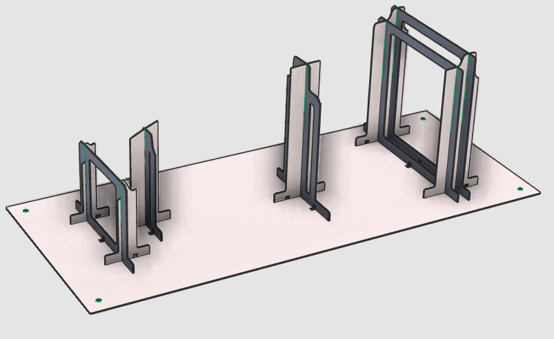
FASTSUITE Edition 2 has a dedicated workbench to easily build a plate based fixture for a specific workpiece.
|
|
|
The initial fixture is directly derived from the workpiece. It will be completed with modification steps of the individual plates and / or changing the number of supporting plates.
After creation the fixture plates are nested onto a sheet and exported, to be manufactured on a 2D laser machine.
|
|
|
|
Steps
|
|
1
|
Preparation
|
1.1
|

|
If the workpiece document has not been loaded into the session, this step has to be executed. Search for the file B_Pillar.cenwpc at the installation folder of this manual.
If already open, the step can be ignored.

|
1.2
|

|
Switch to the Fixture Builder workbench.

|
|
|
|
|
|
2.1
|

|
Build the global fixture.
|
|
|
The fixture will be tuned to meet the design intention.
|
Several different enhancement commands are available, of which some will be highlighted in the next steps.
|
|
3
|
Modify the base plate
|
3.1
|

|
Change the position and orientation of the fixture base plate.
|
|
3.2
|

|
Change the size of the fixture base plate.
|
3.3
|

|
Change the thickness of the fixture base plate.
|
|
1
|
Start the Fixture parameters dashboard by picking the icon in the right dashboard toolbar.
|

|
|
|
The dashboard window appears.
|

|
|
2
|
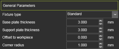
If not open already, click in the General parameters container field to open it.
|
|
|
3
|
Change the Base plate thickness value.
|
|
|
4
|
At the center of the Manipulator, open the Pie menu and pick the Recompute command to rebuild the fixture.
|

|
|
|
|
|
|
3.4
|
|
Change the diameter of the (mounting) hole in the base plate.
|
|
3.5
|

|
Create a text engraving in the base plate. For example a product number.
|
|
3.6
|
|
Modify an existing engraving in the base plate.
|
|
3.7
|
|
Move an existing engraving in the base plate.
|
|
|
4
|
Modify the support plates
|
4.1
|

|
Change the position of a fixture support plate.
|
|
4.2
|
|
Change the orientation of a fixture support plate with dragging the Manipulator.
|
|
4.3
|
|
Change the orientation of a fixture support plate with a given angle value.
|
|
4.4
|
|
Change the size of a fixture support plate.
|
|
4.5
|

|
Remove a fixture support plate.
|
|
New support plates can be added to the fixture. Various possibilities are supported.
|
4.6
|

|
Add a new support plate with a given length.
|
4.7
|

|
Add a new support plate.
|
4.8
|
|
Add two intersecting support plates with a given length.
|
|
4.9
|
|
Add two intersecting support plates.
|
|
4.10
|

|
Split a support plate in two new plates.
|
|
The design of the supports plates (and base plate) is managed over several different attributes. These attributes can be modified to change the global design.
|
4.11
|
|
Modify the plate design over its attributes.
The explanation video below shows an example.
|
|
|
5
|
Save the fixture
|
Optionally the next three steps can be taken to set the name of the fixture. Then following after, the fixture will be saved on disk.
|
5.1
|

|
Switch to the Resource Builder workbench.
|
|
5.2
|

|
Give the fixture an appropriate name.
|
|
1
|
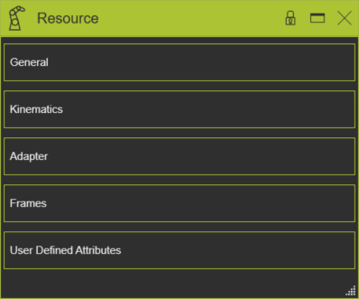
Start the Resource dashboard by picking the icon in the right dashboard toolbar.
|
|
|
|
The dashboard window appears.
|
|
|
2
|
If not open already, click in the General container field to open it.
|
|
|
3
|
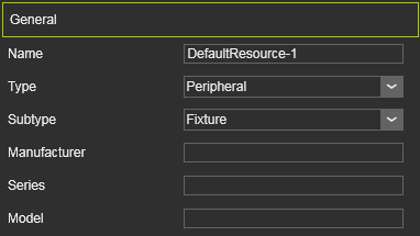
Define the name for the resource by picking the edit field and entering an appropriate name.
|

|
|
|
Leaving the field or closing the dashboard will automatically confirm the change of name.
|
|
|
4
|
Other properties may be edited if wanted.
|
|
|
|
|
5.3
|
|
Switch to the Fixture Builder workbench.
|
|
|
5.4
|

|
Save the fixture.
|
|
1
|
Start the Save fixture command by picking the icon with the left mouse button.
|
|
2
|
A windows file browser appears.
|
|
3
|
Browse to the disk and folder where the fixture (resource) needs to be stored.
|
|
4
|
Accept the name of the fixture, default system name or already modified in the resource dashboard, or change it here when necessary.
|

|
5
|
Confirm saving the fixture by clicking on the Save button.
|

|
|
Alternatively.
When the fixture geometry is needed for other CAx systems, it can be saved also in the formats Parasolid (x_b or x_t) and Step.
|
|
|
6
|
Nest the fixture plates
|
|
All fixture plates are projected and sorted (nested) onto a 2D sheet. This information is used for manufacturing the plates, usually by 2D laser cutting, so that the fixture can be assembled.
|
6.1
|

|
Set the properties for nesting the fixture plates on a sheet.
|
|
1
|
Start the Nesting parameters dashboard by picking the icon in the right dashboard toolbar.
|
|
|
|
The dashboard window appears.
|

|
|
2
|
Set the nesting values for spacing the plates and set the size of the nesting sheet.
|
|
|
|
|
|
6.2
|

|
Nest the fixture plates on a sheet.
|
|
6.3
|
|
Modify the nesting properties.
The explanation video below shows an example.
|
|
|
7
|
Save and export the nesting sheet(s)
|
|
7.1
|

|
Save the nesting.
|
|
1
|
Start the Save nesting command by picking the icon with the left mouse button.
|
|
2
|
A windows file browser appears.
|
|
3
|
Browse to the disk and folder where the nesting (workpiece) needs to be stored.
|
|
4
|
Accept the name of the nesting, default system name or already modified in the workpiece dashboard, or change it here when necessary.
|
|
5
|
Confirm saving the nesting by clicking on the Save button.
|
|
|
|
|
7.2
|
|
Set the properties for the DXF export of the nesting sheet.
|
|
1
|
Start the Nesting parameters dashboard by picking the icon in the right dashboard toolbar.
|
|
|
|
The dashboard window appears.
|
|
|
2
|
If not open already, click in the DXF Export Options container field to open it.
|
|
|
3
|
Set the different options for the DXF export of the nesting sheet.
|
|
|
|
|
|
7.3
|
|
Export the nesting sheet to DXF for offline programming in some external application.
|
|
1
|
Start the Save nesting command by picking the icon with the left mouse button.
|

|
2
|
A windows file browser appears.
|
|
3
|
Browse to the disk and folder where the nesting (workpiece) needs to be stored.
|
|
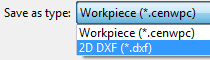
4
|
In the option Save as type set the document type to 2D DXF.
|
|
5
|
Accept the name of the nesting, default system name or already modified in the workpiece dashboard, or change it here when necessary.
|
|
6
|
Confirm saving the nesting by clicking on the Save button.
|
|
|
|
|
|
|
|

|
Be sure to save your data frequently.
|
|
|