3D View background
|
Sets the global background color of the 3D View. Option to specify a single (solid) color or a top down gradient color scheme between two colors.

|

|
Text
|
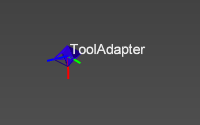
Sets the text color of the 3D Headup display and other text elements.
|
|
Interaction
|
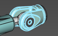
On mouse over
Sets the appearance of an object when hovering the mouse over that object.
Two options are available to specify the final appearance.
|
|
|
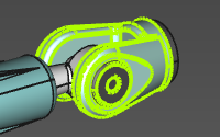
On selection
Sets the appearance of an object when that object has been selected.
Two options are available to specify the final appearance.
|
|
|
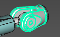
On active object
Sets the appearance of the active object.
Two options are available to specify the final appearance.
|
|
Geometry
|
Display
Sets the color of additional objects, such as a point at the mesh vertex, or a circle center.
|

|
|
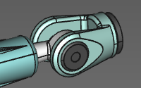
Body edge
Sets the color of the edges of the (exact) geometrical bodies.
|
|
|
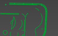
Wireframe
Sets the color of the wire-frame based geometry.
|
|
Kinematic skeleton
|
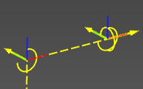
Driven and synchronous joints
Sets the color of the main kinematic chain.
|
|
|
Asynchronous joints
Sets the color of the asynchronous (external) kinematic axes.
|

|
|
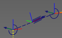
Undriven auxiliary joints
Sets the color of the undriven, auxiliary kinematic chain.
|
|
Machine / Robot reach
|
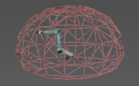
Sets the color of the geometry that describes the reach of a resource, mostly a robot.
|
|
Connections
|
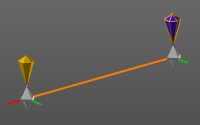
Sets the color of the (adapter) connections.
|
|
Reference - target definition
|
Reference
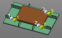
Sets the color of the reference object when relations are being created, for example at calibration.
|
|
|
Target
Sets the color of the target object when relations are being created, for example at calibration.
|
|
Process geometry
|
Programmed process geometry
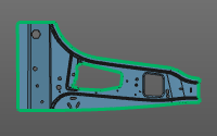
Sets the color of the process geometry that has been used for OLP programming.
|
|
|
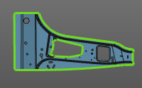
Unprogrammed process geometry
Sets the color of the process geometry that has not been used for any OLP program yet.
|
|
|
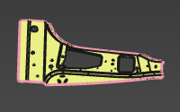
Surface outer boundary
Sets the color of the selected boundary of surface process geometry.
|
|
Program
|
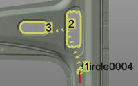
Operation
Sets the color of the operations that are applied on the process geometries and their order.
|
|
|
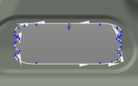
In-process path
Sets the color of the in-process section of the operation.
|
|
|
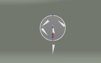
Regular shape in-process path
Sets the color of the in-process section of the operation of a regular shape operation.
|
|
|
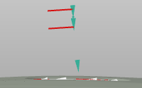
Auxiliary path
Sets the color of the auxiliary section of the toolpath.
|
|
|
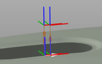
Approach / retract path
Sets the color of the approach and retract sections of the operation.
|
|
|
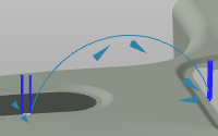
Operation link path
Sets the color of the operation link section of the toolpath, i.e. the motion between two operations.
|
|
Measurement
|
Sets the color of the measurement result objects.
|
|
Grid
|
Sets the color of the grid that is used for layout setup.
|
|