|
|
|
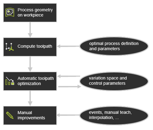
Automated toolpath optimization is a functional package that can help reducing the user's effort in offline programming. Offline programming is normally geared towards achieving an “optimal” process toolpath in terms of:
 avoiding collisions avoiding collisions
keeping the machine / robot system away from singularities and axis limits
ensuring the reachability of the toolpath
aligning the process with reference values and keeping it within specified tolerances
fulfilling other custom guidelines.
|
|
But although the execution evaluates the toolpath and potentially optimizes any individual position, it will preserve explicitly defined (manual) programming events and will not overwrite them, such as:
teach events
manually taught positions
interpolations
jolt optimizations
suppressed positions.
|
|
With this information in background one could sketch the workflow of toolpath creation and the step of when to apply the automatic toolpath optimization as in the picture below.
|
|
|
|
|
|
|
|
|
Quality criteria are defined to validate the computed toolpath. Each of them with ranges to indicate the level of quality, i.e. the level of acceptance of the toolpath. For each position of the toolpath the quality will be analyzed and displayed in the dashboards and in the 3D space.
|
|

|
|
|
|
|
|
|

|
Unreachability
|
Evaluates unreachable situations of the robot or machine.
|
Good or invalid.
|
The evaluation against this criteria is always being performed.
|

|
Collision
|
Evaluates collision situations.
|
Good or invalid.
|
The evaluation against this criteria is only being executed when the Collision analysis switch in the simulation player toolbar has been activated.
|

|
Singularity
|
Evaluates singularity situations of the robot or machine.
|
Good or invalid.
|
The evaluation against this criteria is always being performed.
|
|
|
|
|
|

|
Process angle deviation
|
Evaluates the process angle deviation from its reference value.
|
Angle ranges from good to invalid.
|
|


|
Tool angle deviation
(arc welding technology)
|
Evaluates the tool angle deviation from its reference value.
|
Angle ranges from good to invalid.
|
It replaces the process angle deviation criteria.
Only applicable when 6-axis robots are being used.
|


|
Travel angle deviation
(arc welding technology)
|
Evaluates the travel angle (tangent direction) deviation from its reference value.
|
Angle ranges from good to invalid.
|
It replaces the process angle deviation criteria.
Only applicable when 6-axis robots are being used.
|


|
Work angle deviation
(arc welding technology)
|
Evaluates the work angle (bi-tangent direction) deviation from its reference value.
|
Angle ranges from good to invalid.
|
It replaces the process angle deviation criteria.
Only applicable when 6-axis robots are being used.
|
|
|
|
|
|

|
Axis limit proximity
|
Evaluates the proximity to the limits of the driven axis.
Separated evaluation value range for linear and circular joint axis.
|
Linear distance or angular ranges from good to invalid.
|
|

|
Axis speed
|
Evaluates the axis speed of all driven axis as a (absolute) difference between the start and the end motion between positions.
|
Percentage ranges from good to invalid.
|
|
|
|
In here is defined which quality criteria are actually applied and to what warning or critical values they are validated. Criteria can be de-activated from the evaluation by pressing their On /Off button. The validation values can be modified by dragging the slider over the bar or entering the new values.
|
|
Any modification here will update the analysis dynamically. The new result will be shown immediately after update.
|
|
|
|
|
|
|
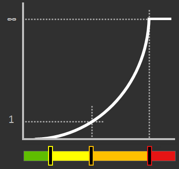
To be able to compare different toolpath situations, the quality of the toolpath is also being expressed in a costs factor. This is a neutral value, not any sort of currency.
|
|
Each target criteria has been given a certain costs function. This can be a linear, a parabolic function or anything else, as the example below shows.
|
|
|
|
The quality range equals a costs value of:
|
|

|
Good (green)
There are no costs; i.e. costs are 0.
|

|
Acceptable (yellow)
Costs value between 0 and 1.
|

|
Critical (orange)
Costs value from 1 up to infinite (∞).
|

|
Invalid (red)
Costs are infinite (∞).
|
|
|
At each toolpath position these costs are calculated for each analyzed criteria and then summed up. To avoid the influence of having different number of toolpath positions, depending on different kind of modifications, such as the approximation of the underlying geometry, each individual position costs is multiplied by the distance of the toolpath of that position. Finally, the total costs of an operation is the sum of its individual position costs. This is then done for each operation, each operation group and finally for the complete program.
|
|
|
|
|
|
|
The automatic toolpath optimization can be executed on the whole program or just on an operation group or operation. It is started in the pie menu in the Active program or Toolpath monitor dashboard.
|
|

|
|
|
|
|
|
The automatic toolpath optimization uses a methodology of iterative steps to find the optimal result. These iterative steps are applied to a set of variables, i.e. attributes of the toolpath that can be modified during the optimization.
|
|
In each iteration step, a range with a number of variations is being built to find the optimum result (= minimal costs) within that range. From that optimum, a new range is being defined from the variation before to the variation after that found optimum. That range again is divided in smaller steps to search for the optimum again.
This process repeats itself until the variation step equals (or is smaller than) the discretization step of the variable or when any other boundary condition has been met.
|
|
This process is executed for each of the variables. But each of these variables might give a different optimal toolpath orientation. Therefore, the resulting optimized toolpath position will be a compromise between the results of the individual variables.
|
|
In the end, the automated path optimization evaluates the whole toolpath; i.e. the range (program, group or operation) that has been selected and tries to find an optimized solution that matches with the given quality criteria and results in minimum costs.
|
|

|
|
|
|
|
|
|
|
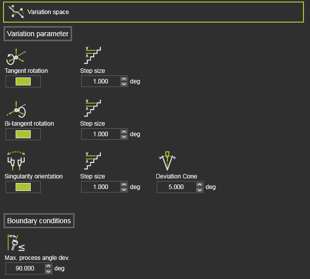
The Variation space defines what modifications can be made to the toolpath elements to search for the optimal solution, i.e. minimal costs. It shows all variables that can be included in the optimization process, their range within they can be varied and the distribution step or discretization within that range.
|
|
For most technologies or scenarios the default variation space values should do the job; nothing to change here when you are not that familiar with the meaning of these variables.
|
|
The variables here might be specific for a technology or a certain technology setup in combination with an OEM brand controller and robot or machine. In other words; the exact content of the container might look different for each case.
|
|
The most common variables are:
|
|
|
|
|
|
|

|
Tangent rotation
|
Varies the toolpath position while rotating it around its tangent direction.
|
Step size
Rotation value in each iteration step.
|
Switch to include it in the optimization process.
|

|
Bi-tangent rotation
|
Varies the toolpath position while rotating it around its bi-tangent direction.
|
Step size
Rotation value in each iteration step.
|
Switch to include it in the optimization process.
|

|
Singularity orientation
|
Evaluates singularity situations of the robot or machine.
In case of a robot scenario, the singularity orientation means the rotation of the toolpath position around its normal axis.
|
Step size
Rotation value in each iteration step.
Deviation cone
Axis with values within the specified cone angle are being optimized.
|
Switch to include it in the optimization process.
|

|
Normal rotation
(arc welding technology)
|
Varies the toolpath position while rotating it around its normal direction.
|
Step size
Rotation value in each iteration step.
|
Switch to include it in the optimization process.
|
|
|
The Boundary conditions section includes additional parameters that can be introduced to limit the amount of variations. Where normally the tangent and bi-tangent rotation of the toolpath position can vary between -180 and +180 degrees, cause these parameters extra conditions to allow the tangent and bi-tangent axis to rotate only within the range and as long as the boundary condition is still met.
|
|
|
|
|
|
|

|
Max. process angle deviation
|
The maximum allowed process angle deviation from the reference direction.
|
|
An optimization result is accepted when the process angle is smaller or equal to this value.
This condition can only be applied when its corresponding criteria Process angle deviation has been disabled from the quality evaluation.
|


|
Max. work angle deviation
(arc welding technology)
|
The maximum allowed work angle deviation from the reference direction.
|
|
It replaces the process angle deviation criteria.
Only applicable when 6-axis robots are being used.
|


|
Max. travel angle deviation
(arc welding technology)
|
The maximum allowed travel angle deviation from the reference direction.
|
|
It replaces the process angle deviation criteria.
Only applicable when 6-axis robots are being used.
|


|
Max. tool angle deviation
(arc welding technology)
|
The maximum allowed tool angle deviation from the reference direction.
|
|
It replaces the process angle deviation criteria.
Only applicable when 6-axis robots are being used.
|
|
|
|
|
|
|
|
|
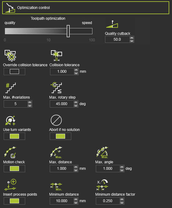
The Optimization control is a set of attributes to manage the optimization process.
|
|
|
|
|
|
|
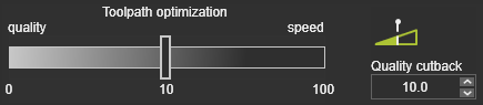
Heuristic parameter to balance between best result and fastest computation time.
|
The value can be interpreted as cost tolerance per meter toolpath.
A value of 0 would result in the global best result, i.e. lowest costs, regardless the required computation time.
A value of 1 would mean that even a toolpath having higher costs up to 1 per meter in average would be acceptable as optimization result, though there would be better results with lower total costs.
|
|
In the standard optimization process, each toolpath position is analyzed against the collision tolerance that has been set in the simulation settings.
|

|
Override collision tolerance
|
Option to override the simulation collision tolerance.
|
With this switch, the tolerance from the simulation settings will be ignored and replaced by the new defined collision tolerance here.
|

|
Collision tolerance
|
The collision tolerance while running the optimization.
|
The tolerance between two groups for a collision to be detected. The value is the checking distance between the groups.
A value = 0 corresponds to a contact.
|
|

|
Max. # variations
|
Divides the range in a maximum number of variations, i.e. step size.
|
|

|
Max. rotary step
|
The maximum allowed rotation step per variation of the robot / machine axis.
|
|

|
Abort if no solution
|
Terminates the optimization.
|
To prevent unnecessary long computation times, the optimization process will be aborted when on the first iteration step no solution has been found.
|
|
If the resource has limited rotary axis, closed contour geometry can lead to unwind situations depending on start point and process direction.
|

|
Use turn variants
|
Prevent unwind situations by selecting proper turn values for the first process point.
|
Limited to one turn value below and one above the default turn value.
Turn variants will be not considered, if the turn value is already set for the first process point.
|
|
The automatic toolpath optimization builds an optimized toolpath based on the incident validation at the toolpath positions and the via points on circular toolpath sections. It cannot prevent that in between these toolpath positions the trajectory still encounters some incident issue, because the trajectory itself cannot be evaluated.
With using the motion data of the toolpath, the algorithm can define intermediate points between the toolpath positions and evaluate them for incidents. The quality evaluation on these intermediate points restricts for incidents on collision, reachability and singularity.
|

|
Motion check
|
Switch to activate the motion check, i.e. to define intermediate points between toolpath positions.
|
|

|
Max. distance
|
The maximum Cartesian distance between two consecutive points to be checked.
|
|

|
Max. angle
|
The maximum angular 'distance' between two consecutive points to be checked.
|
|
|
Toolpath quality is measured in costs. Incidents on toolpath positions, or between the positions normally increase these costs. The automatic optimization can identify the area of impact of these incidents. By trying to limit such area, the costs will reduce.
This can be achieved by adding, inserting additional process points on the toolpath around these critical areas.
|

|
Insert process points
|
Switch to enable to insert additional process points.
|
|

|
Minimum distance
|
The minimum Cartesian distance between two process points.
|
Measured between two inserted process points or between the inserted process point and an existing one.
|

|
Minimum distance factor
|
The minimum distance as factor of the local process speed.
|
Measured between two inserted process points or between the inserted process point and an existing one.
|

|
The inserted process points belong to the automatic optimization data. This means that when running another optimization, removing the optimization data or anything else that causes a recomputation of the initial toolpath, these inserted process points will be deleted.
|
|
|
|