|
|
|
Before doing any toolpath optimization, manually or automatic, before computing the initial toolpath in general, it is essential to have the project well prepared. This concerns:
|
|
|
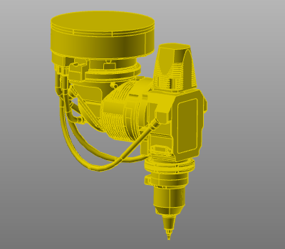
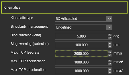
Axes of machine, robot and / or external resource
|
|
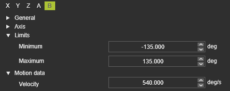
 Make sure that the axis limits of the resource are specified correctly to correspond with the real physical device. Obviously this applies to all the axes of the resource. Make sure that the axis limits of the resource are specified correctly to correspond with the real physical device. Obviously this applies to all the axes of the resource.
|
|
|
|
The same applies to the maximum speed value (Velocity) of the axes.
|
|
|
|
|
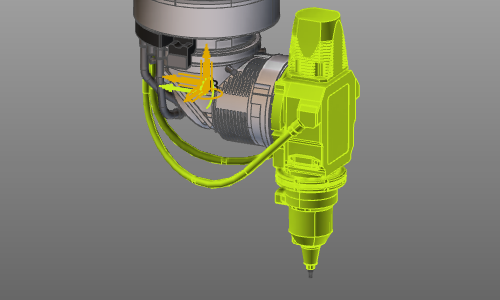
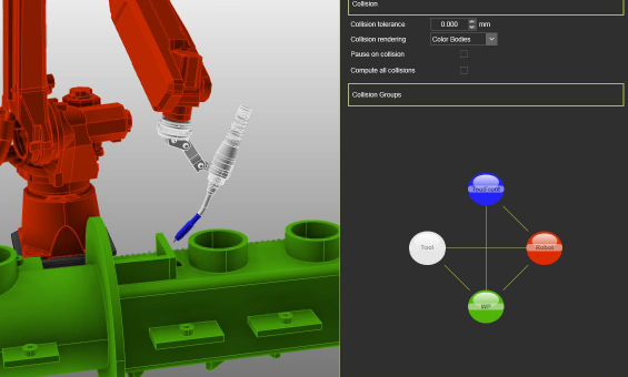
Collision group definition and analysis
|
|
|
Define the collision groups in such a way that there will not be a permanent collision between groups. An optimized solution will never be found in that case.
|
|
|
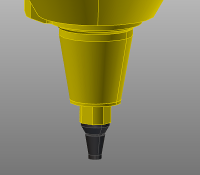
Exclude unnecessary geometry form the collision groups. This will speed up the process and thus the computation time of automatic toolpath optimization. For example this can be the front tip of a cutting laser head or the welding wire of the arc weld gun.
|
|
|
|
|
|
Verify the group pairing of what objects are being analyzed against each other.
|
|
|
|
|
|
Verify to not have any hidden collisions anywhere in the scenario during simulation. The toolpath optimization will return with a possibly unexpected, non-visible collision occurrence.
|
|
|
Programming parameters
|
|
|
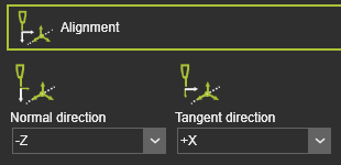
Set the programming parameters to match with the ideal process situation. Depending on the applied technology or equipment, some care to be taken to for example:
•The tool alignment
•The process angles. |
|
|
|
|
|
|
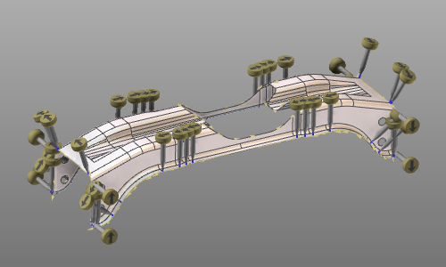
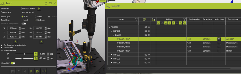
Define clear starting positions for the machine or robot, as well as for external axes (resources):
•External axes with explicitly defined values at least at the very first toolpath element in the program.
•A PTP motion to the very first position in the operation.
•Approach and retract positions to be defined with the motion type "Approach" and "Retract". |
|
|
|
|
|
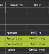
Define proper speed values at the toolpath positions. Process positions should not have zero (=0) speed.
|
|
|
|
|
|
Toolpath quality definition
|
|
This step is recommended at this stage but not mandatory. Because the quality evaluation is executed dynamically at any time, the quality definition therefore can also be set or adjusted at later time.
|
|
The definitions and parameters can be found in the Toolpath quality tech tab on the Programming defaults dashboard or Active program dashboard.
|
|
|
|

|
|
When needed, modify the threshold values of the required attribute, e.g. the maximum allowed process angle deviation.
|
|
|
Activate the target criteria that are relevant for the toolpath quality. Normally, the system defaults should work fine initially for most common scenarios.
For arc welding: the Tool angle deviation might be activated if the initial tool angle should be the preferred orientation.
|
|
|
|
Set the target criteria threshold values to match the specific project or user requirements:
•Usually the angle deviation maximum values (red „no go“ threshold) will be adjusted.
•Axis speed „no go“ values (where available) should be kept to 100% in most cases. This will ensure that the TCP speed on process sections is not being reduced due to too strong axis motions. |
|
|
|
Compute toolpath
|
|
After completing the above mentioned preparation steps, the toolpath can be computed and its result can be validated.
|
|
|
|
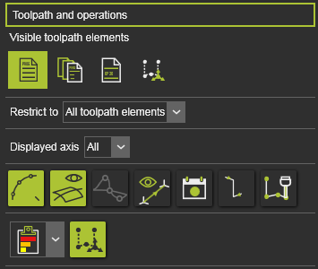
Make sure to switch on the corresponding display filters to see the quality evaluation and other toolpath specific information.
|
|
|
|
|
|
|
|
|
Collision validation
|
|
|
|
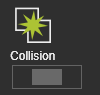
Although the Collision validation activation is displayed in the panel of the Evaluation criteria, it cannot be modified there. In the simulation player bar the button has to be pressed to actually activate the collision analysis. Only then the collision analysis will be executed.
|
|

|
|
|
|
|
|
|
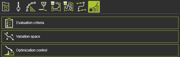
Variation space
|
|
Usually there is nothing to adjust here. A few things to keep in mind:
|
|
|
|
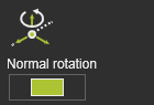
The variation of the normal rotation might be de-activated, when the tool angle should not be modified. This will speed up optimization calculation but reduces the possibilities in modifying the toolpath positions in order to solve collisions or unreachable positions. It also might reduce the overall toolpath quality.
|
|
|
|
|
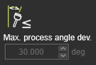
The boundary condition Maximum process angle deviation by default is not editable. This is because its corresponding quality criteria has been switched ON for the toolpath evaluation. The optimization will then use that critical threshold value to find the optimal solution.
|
|
|
Optimization control
|
|
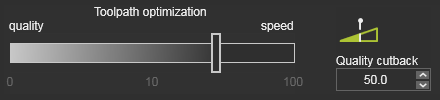
Quality cutback
|
|
|
|
To speed up the optimization process in general, the Quality cutback attribute comes in place. With this attribute a balance between finding the most optimal result and the fastest computation time is made. When using this attribute (values > 0), the iteration step of the methodology will no longer search for the optimal solution within that step, but will stop already when an iteration result meets the requirements, although that result might not be optimal. The sooner that decision can be made, the less computation time will be needed to come to a final result. Obviously because that final result might not be the global optimum, the result quality will be lower, i.e the resulting evaluation costs are higher than optimal.
|
|
You may lower this value later on to get higher quality results, but at costs of longer calculation times.
|
|
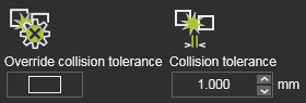
Collision tolerance
|
|
|
|
With the Override collision tolerance activated, the global value will be ignored for the optimization process. A new value has to be specified here. Set a higher value here than in the simulation settings to get a more safe result, because the path optimization does not consider flyby motion effects. Therefore, optimization with some collision tolerance will consider some safety distance.
|
|
Collision result
|
|
The result of the optimization might still show some collisions between two consecutive toolpath elements when you run a simulation. The automatic toolpath optimization algorithms currently considers only the program process positions, not some intermediate positions that are the result of the approximation calculation. Try to use the Override collision tolerance to reduce this risk.
However, it may be necessary to rework some parts of the toolpath manually afterward. We plan to optimize the intermediate positions in a next release.
|
|
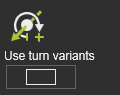
Use turn values
|
|
|
|
For robot axis, to consider the multiple turn against of the axis. This may leave unsolved unwind situations in linear or circular motions, where a robot cannot move along.
|
|
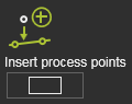
Insert process points
|
|
|
|
Automatic insertion of process points may improve the toolpath quality results and may lead to lower computation times.
|
|
|
|
|
|
|

|
First of all; it has to be understood that the automatic optimization might not always find a better result, or might find no result at all.
|
|
|
|
|
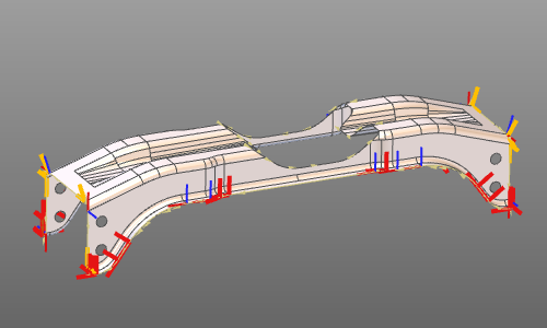
In the optimized toolpath position, the robot axis rotates by more than 180 degrees, which still leads to collisions. The robot runs into axis limit which can only be solved by starting in a different turn range for this axis (unwind situation). Activate the Use turn values control to enable this
|
|
|
|
In the above case with the control enabled, there are still some unwind situations.This may be caused by the fact the the optimization will only solve the problem for the process points of the toolpath. The problem however might occur at the approach. With use of the programming attribute CTS Backpropagation, the optimized process point turn is applied to the approach points too.
|
|
|
|
Zero speed at the process points causes optimization errors, which can be read in the log window.
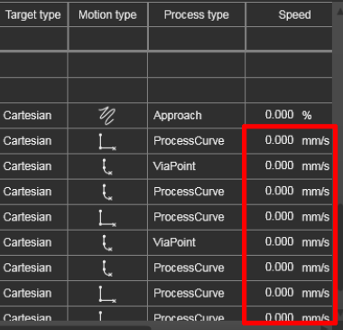 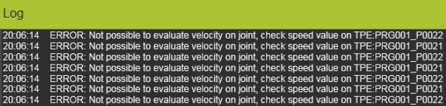
The optimization requires a correctly defined speed at all process points.
|
|
|
|
Running a simulation after a successful, collision free optimization stops with a collision. This is because in between two positions the motion might run into collision after all. With the Motion check control, the motion data of the toolpath can be used and analyze them for incidents.
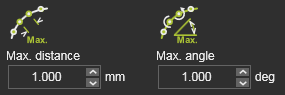
Even then, in some rare cases collisions with very small parts of objects are not considered during the optimization. They can be missed due to the defined intermediate motion step resolution. Use smaller values for the Max. distance and / or the Max. angle attributes in the motion checking options.
|
|
|
|
After a successful optimization with motion check, the simulation still shows some collision. This is because the simulation cannot consider the accuracy of the flyby motion while analyzing for collision. The simulated motion can be slightly different compared to the exact toolpath positions in the motion data. A larger collision tolerance might solve the problem.
A good value for the tolerance is the same value as that has been programmed for the flyby distance. Take care that a high value most probably lead to collision finding anywhere.
|
|
|
|
Motion failures happen after an optimization. This can happen for Fanuc robots simulated in E2. Or there is still an imperfect motion emulation in E2, that can cause unexpected motion failures, e.g. in CIR motions or when two toolpath elements lie very close to each other.
A solution is to suppress one of these elements that lies close to the other. And activate the Insert process points control.
|
|
|
|
The automatic optimization is not able to analyze and optimize the toolpath for different robot configurations. It may happen that for the current configuration, the optimization does find a solution. The user must take care to set a proper robot configuration upfront the optimization.
|
|
|
|
On scenarios that include external axes (i.e. resources) it is required that the axes values are explicitly defined at the beginning of the program. If not, the optimization may run on the operation that uses these axes, but will fail on the complete program.
|
|
|
|
Running the optimization with the Insert process points control activated will usually result in improved toolpaths. However, in some rare cases this control in combination with the Quality cutback > 0 may result in higher costs, because the optimization chooses other variants. This side effect cannot be avoided. Therefore it is recommended to set Quality cutback = 0 in combination with the Insert process points control.
|
|
|
|
Be aware that manual teach and manually defined interpolations are not being analyzed and recomputed.
|
|
|
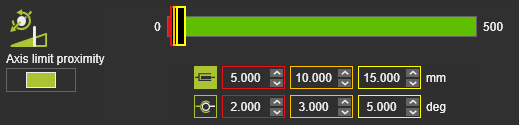
When you cannot run the process at the maximum axis proximity, change the threshold values of the quality criteria of that parameter. Increase the critical proximity value from zero (=0) to 5mm for example.
|
|
|
Low axis speed results in easy and smooth motion along the toolpath. But impacts the process angle deviation.
|
|
|
The speed (of the tool frame) along the toolpath is the result of the axis speed. Optimizing against 100% of the axis speed controls this path motion.
|
|
|
In some specific machining scenarios, a configuration change correction is done along a sequence of toolpath elements during the optimization. This happens element by element in subsequent sub-iterations. This is also repeated on higher iteration levels, leading to long(er) calculation times.
|
|