Some recommendations, considerations and potential issues to keep in mind while working with the operation link path.
|
|
|
|
|

|
Please note that manually taught toolpath elements and interpolation sections are not optimized.
|
|
|

|
When you cannot run the process at the maximum axis proximity, change the threshold values of the quality criteria of that parameter. Increase the critical proximity value from zero (=0) to 5mm for example.

|
|
|

|
Low axis speed results in easy and smooth motion along the toolpath, but impacts the process angle deviation.
|
|
|

|
In some specific machining scenarios, a configuration change correction is done along a sequence of toolpath elements during the optimization. This happens element by element in subsequent sub-iterations. This is also repeated on higher iteration levels, leading to long(er) calculation times.
|
|
|

|
The speed (of the tool frame) along the toolpath is the result of the axis speed. Optimizing against a maximum axis speed value of 100% will avoid the need to reduce the TCP speed.
|
|
|
|
|
|
|

|
First of all; it has to be understood that the automatic optimization might not always find a better result, or might find no result at all.
|
|
|

|
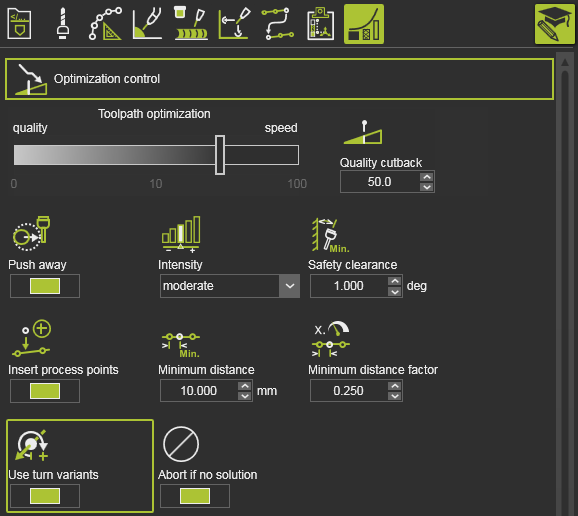
In the optimized toolpath position, the robot axis rotates by more than 180 degrees, which still leads to collisions. The robot runs into axis limit which can only be solved by starting in a different turn range for this axis (unwind situation). Activate the Use turn values attribute in the Optimization control to enable this.
|
|
|

|
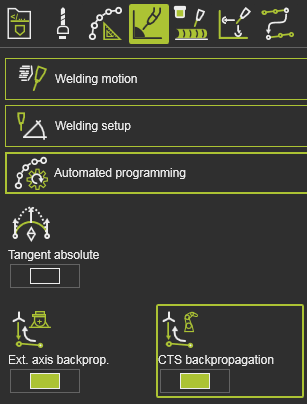
In the above case with the control enabled, there are still some unwind situations.This may be caused by the fact the the optimization will only solve the problem for the process points of the toolpath. Different turn values at the process points will override the optimized value at the first process point. With use of the programming attribute CTS Backpropagation, the optimized process point turn is applied to the approach points too.
|
|
|

|
Zero speed at the process points causes optimization errors, which can be read in the log window.
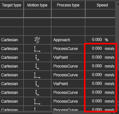 
The optimization requires a correctly defined speed at all process points, when using the Axis speed target criterion for optimization.
|
|
|

|
After a successful optimization with motion check, the simulation still shows some collision. This is because the simulation cannot consider the accuracy of the flyby motion while analyzing for collision. The simulated motion, with flyby considered, can be slightly different compared to the motion data used in APO where the exact TPE coordinates are used. Use the Push away attribute to increase the distance between possible colliding objects.

When the push away effect has become too large, e.g. the distance between the objects is too large or the resulting costs have been increased too much, re-run the optimization with a lower intensity to reduce its impact.
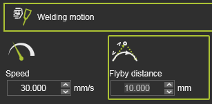
Also have a look at the Flyby distance. Sometimes it is set unnecessarily high. Reduce the programed value.
|
|
|

|
Running a simulation after a successful, collision free optimization stops with a collision. This is because on intermediate motion between two positions it might run into collision after all.
In some rare cases collisions with very small parts of objects are not considered during the optimization. They can be missed due to the defined intermediate motion step resolution.
Use smaller values for the Max. distance and / or the Max. angle attributes in the motion checking options. Note that this can increase the calculation time.

|
|
|

|
Motion failures happen after an optimization. This can happen for Fanuc robots simulated in E2. Or there is still an imperfect motion emulation in E2, that can cause unexpected motion failures, e.g. in CIR motions or when two toolpath elements lie very close to each other.
A solution is to suppress one of these elements that lies close to the other.
And activate the Insert process points control.

|
|
|

|
The automatic optimization is not able to analyze and optimize the toolpath for different robot configurations. It may happen that for the current configuration, the optimization does find a solution. The User must take care to set a proper configuration at the start of each operation before running the APO.
|
|
|

|
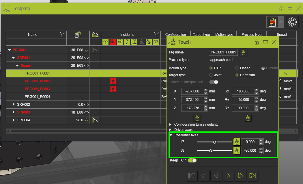
On scenarios that include external axes (i.e. resources) it is required that the axes values are explicitly defined at the beginning of the program. If not, the optimization may run on the operation that uses these axes, but will fail on the complete program.
|
|
|

|
The criterion of the Axis proximity limits verifies the inverse kinematic chain of the manufacturing resource for safe values of its axes and not to run into their limits. The verification includes also the (axes of the ) external resources that are connected to the controller. And although these axes typically are being used at their limit positions, the APO takes them into account. This may lead to longer computation time and the final optimization result may not be as good as optimal.
|
|
|

|
Running the optimization with the Insert process points control activated will usually result in improved toolpaths. However, in some rare cases this control in combination with the Quality cutback value larger than 0 let AP choose other variants that may lead to higher costs.
This side effect cannot be avoided, as this is a side-effect of the characteristics of the Quality cutback approach. Therefore it is recommended to set Quality cutback = 0. This will also avoid unexpected higher costs in combination with the Insert process points control set to On.

|
|
|

|
The optimization runs longer than expected. There are several reasons to cause this:
•At first, this can occur if there are lots of collisions and only a few collision-free possibilities in the solution space. In this case, the algorithm searches for more possible solutions in a finer grid, which requires more calculation time. In the worst case, there is no solution at all and it will take some time to find out.
•Then it may also be due to the complexity of the cell and, related to it, the computational effort required for the collision detection.
•The best optimization results are achieved when the value for Quality cutback is set (close) to 0. However, this comes with a consequence of a longer calculation times.
•If the external axis values are set to an axis limit (or very close to it) and the Axis limit proximity evaluation criteria is active, this can also lead to longer calculation times.
Possible solutions or workarounds are:
•There is no general solution/workaround. The more demanding the task, the longer it takes to find a solution. You can try to reduce the number of variation parameters in the variation space. However, this can lead to no solution at all, as the solution space is then even more limited.
•Simplify the collision checking: check whether some of the collision check relationships can be deactivated or whether collision groups can be simplified or removed completely.
•Run the optimization with a high Quality cutback value first, to ensure that there is a solution in shorter time.
•Move the external axis a little away from the axis limits. E.g., into the ideal (green evaluation) range. |
|
|
|
|
|
|
Current functional limitations to consider when using the Automatic process path optimization.
|
|

|
Available for the following technologies:
•Arc welding
•Laser welding
•Laser cutting |
|
|

|
Automatic process path optimization does not optimize operation approach and retract positions. Users must modify them manually afterward to make them collision-free.
|
|
|

|
External axis are not modified. Users must program external axis before running the optimization to make path positions principally reachable.
|
|
|

|
In laser cutting: non-exploded regular shapes (regshapes) are not optimized. Users must optimize the regshapes manually or explode them before running the optimization.
|
|
|

|
In arc welding: seam calibration touch positions are not optimized. Users must analyze and optimize these positions manually when necessary.
|
|
|

|
In robotics, only the current set configuration is used for optimization. Alternative, possible better configurations, must be specified at OP start explicitly by the user.
|
|
|