Purpose
|
|
FASTSUITE Edition 2 distinguishes between the workpiece and the fixture resource. The workpiece will be built from an external file containing the part geometry.
|
|
|
The specific workpiece document will be generated. Geometry from the external file will be imported to give shape to the part. Then dedicated information is assigned to be able to start any offline programming at later stage of the project. And finally the workpiece is completed in such way that it can be easily loaded and handled in a fixture and workcell layout where it is going to be processed.
|
|
|
|
Steps
|
|
|
|
1.1
|

|
Switch to the Workpiece Preparation workbench.

|
|
|
1.2
|

|
Create a new, empty document.
If another document is already open in the running session, this step has to be executed. If not, this step can be skipped
|
|
|
|
|
2.1
|

|
Verify the Settings for importing geometry.
To use the workpiece properly in offline programming it is mandatory to import the geometry as exact geometry.
|
|
2.2
|

|
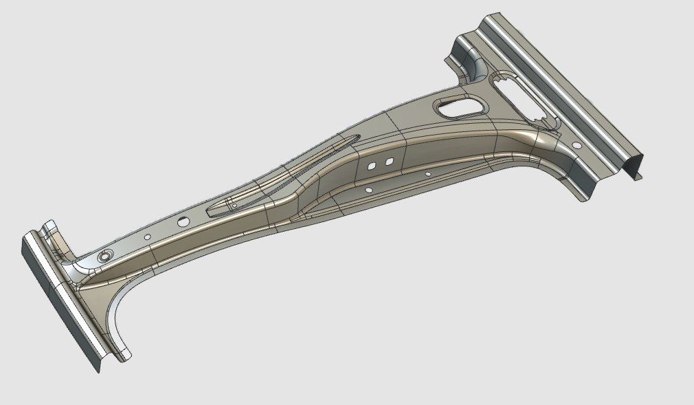
Import the geometry from the file B_Pillar.stp, which is located on the installation drive of this manual.

|
|
2.3
|

|
Create a new workpiece for the imported geometry.
|
|
|
3
|
Build the workpiece shape
|
|
3.1
|

|
For the following step the geometry has to be selected. The software supports various ways to do this, including multi-selection of geometrical elements.
Selection with trap
Double click selection
|
3.2
|

|
Attach the part geometry to the workpiece document.
|
|
1
|
Start the Attach geometry command by picking the icon in the left workbench toolbar.
|

|
|
2
|
In the 3D View select the geometry that represents the workpiece.
|
|
|
3
|
Add the geometry to the workpiece.
|
|
|
|
|
|
4
|
Define the process geometry
|
|
Create process geometry elements on the cutting contours.
|
4.1
|

|
Set the process geometry contour search mode to automatic.
|
|
4.2
|

|
Create the process geometry of the part contours.
|
|
|
5
|
Complete the workpiece (if needed)
|
5.1
|

|
Create a mechanical plug (child) adapter as reference to easily place the workpiece on the fixture. Use a common, typical position between the workpiece and its fixture, like a fixation hole or such, where to define the adapter.
|
|
1
|
Start the Adapter command by picking the icon in the left workbench toolbar.
|

|
|
|
The Manipulator is placed in the 3D View origin.
|

|
|
2
|
If needed, move the Manipulator to that position where the adapter has to be created.
|
|
|
3
|
Open the Pie menu on the center of the Manipulator.
|

|
|
4
|
Start the Create adapter command to open the sub level.
|

|
|
5
|
In the Pie of available adapters pick the Mechanical plug (child) adapter.
|

|
|
|
The mechanical plug adapter has been created. Close the Manipulator or move it away to see to better see the result.
|

|
|
|
|
|
|
|
|

|
Or alternatively, reposition the existing default adapter of the workpiece.
|
|
1
|
Start the Adapter command by picking the icon in the left workbench toolbar.
|
|
|
2
|
Pick the adapter that is going to be moved and open the Pie menu.
|
|
|
3
|
Pick the Move adapter command.
|
|
|
|
The Move Manipulator is placed at the adapter.
|

|
|
4
|
Move the Manipulator to the new position (and orientation) of the adapter.
|
|
|
5
|
Confirm the new position by opening the Pie on the Manipulator's center and picking the Manipulator Reset command.
|

|
|
|
|
|
|
|
|
6.1
|
|
Give the workpiece an appropriate name.
|
6.2
|

|
Save the completed workpiece.
|
|
1
|
Start the Save As command by picking the icon with the left mouse button.
|
|
2
|
A windows file browser appears.
|
|
3
|
Browse to the disk and folder where the resource needs to be stored.
|
|
4
|
Accept the proposed name of the workpiece, default system name or already modified in the dashboard, or change it here when necessary.
|

|
5
|
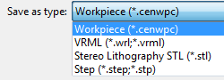
In the option Save as type select the document format in which the resource has to be stored.
|
|
6
|
Confirm saving the workpiece by clicking on the Save button.
|

|
|
|
|
|

|
Be sure to save your data frequently.
|
|
|