Overview
|

The software knows many different objects, all with their specific content, such as geometrical elements, kinematic chains, connection adapters, process geometry, etc. All these objects can be displayed or hidden in the 3D View without needing to select them (individually). The software in principle automatically displays the workbench specific and required objects.
|
|
The Display filter command opens a set of toggle filters to display or hide groups of objects. It will automatically grabs all the features of that specific group of objects. When the group of features is shown, the corresponding toggle icon is highlighted (green background color). In contradiction to the Swap Show/Hide operation, this filter command does not switch between workspaces, nor does it move the object between the workspaces. It only sets the display of the objects in the workspace active or de-active.
|
|
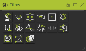
|
|
Kinematic skeleton

|
|
The kinematic skeleton visualization can be switched off with the Show the skeletons button.
|
|
|
|
|
Sensors

|
|
The sensor visualization can be switched off with the Show the sensors button. It effects all sensors of any type in the current workspace.
|
|
|
|
|
|
Adapters

|
|
The adapter visualization can be switched off with the Show all adapters button.
|
|
In the Adapter classes options, the selection for displaying or hiding the adapters is separated between electrical and mechanical adapters. Thus, they can be visualized independently from each other.
|
|

|
|
|
|
|
Cameras

|
|
With the Show the cameras button the camera symbols are displayed or hidden.
|
|
|
|
|
Frames

|
|
With the Show all frames button the frames (i.e. coordinate systems) are displayed or hidden. In the Frame types option, the visualization state can be set for each different type of frame.
|
|

|
|
From left to right can be picked in the selector row to show or hide the:
 world origin world origin
 root frame root frame
 base frame base frame
 tool frame tool frame
 technology reference technology reference
 auxiliary axis systems. auxiliary axis systems.
|
|
|
|
|
Inactive elements

|
|
This display filter becomes useful in the OLP workbench. When the layout is built from many components and several OLP programs have been created, the Hide the inactive elements displays only those components (resources, controllers, etc.) that are involved in the active program.
|
|
|
|
|
Toolpaths

|
|
With the Show the toolpaths button the toolpath elements are displayed or hidden.
|
|
|
|
|
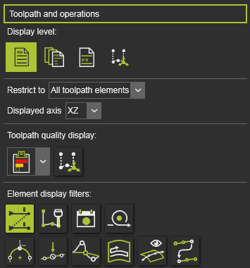
The Toolpath and operations options include additional features to show (parts of) the toolpath.
|
|
|
|
|
Display level
|
|
This is an option that can be used when teaching and simulating the toolpath. By default the program content is displayed. But one can switch to set the focus of display on operation groups of the program, the operations or on the individual toolpath elements. Displaying with focus on one of these sub levels of the program activates a slider in the filter interface. With the slider, the number of following elements (operation or operation groups) in both directions, as seen from the current element, are displayed. The other elements are hidden.
|
|
The slider corresponds with the number of elements along the toolpath. At the most left position there will be one following element shown. The slider at its most right position shows all the toolpath elements.
|
|
|
|
|
|
Restrict to
|
|
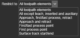
This is an additional option to restrict the toolpath display to certain elements of the toolpath. In the drop down selector the restriction option can be picked and set.
|
|
|
|
Example:
|
|
|
|
|
|
Displayed axis
|
|
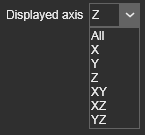
With the option one can pick from the drop down selector which axes of the toolpath element are being displayed..
|
|
|
|
Example:
|
|
|
|
|
|
Toolpath quality display
|
|
These options are used to display the toolpath quality evaluation incidents.
|
|

|
|
From the drop down list the preferred display level can be set.
|
|

|
Display only the failure level.
|

|
Display the failure and critical levels.
|

|
Display all quality levels.
|
|
|
With the option button at the right side of the display level, the incidents are marked on the 3D toolpath.
|
|

|
|

|
The quality display on the 3D toolpath can also be turn on or off with the keyboard shortcut  . .
|
|
|
|
Element display filters
|
|

|
|
With the Show / Hide the operation sequence lines and numbers option the operation sequencer information is being displayed or hidden. The operation visualization itself is not effected.
|
|
|
|
|
|

|
|
With the Show / Hide the tool representation option a 3D representation of a tool is being displayed or hidden at the toolpath positions. This representation shows the position and orientation of the tool.
|
|
There are two representations available; an welding torch for the arc welding technology and a default tool for all other technologies. The cad models, in JT format, are located in the folder <install folder>\Resources\Models\Widgets\Technology in the installation folder.
|
|
|
|
|
|

|
|
With the Show / Hide the toolpath element symbols option the event symbols are displayed or hidden.
|
|
|
|
|
|

|
|
With the Show / Hide the operation cycle as representation option some toolpath (operation) cycles will be displayed as an ordinary toolpath with toolpath elements or as alternative representations, to minimize the amount of toolpath elements that are displayed.
|
|
The arc welding touch positions make use of this filter capability
|
|
|
|
|
This representation display however only applies to all unselected operations. The touch operation that has been picked, either in the 3D space or in a dashboard, will automatically be displayed with the standard toolpath axes to show all its individual positions.
|
|
|

|
|
With the Show / Hide the via points option the toolpath (circular) via point elements can be displayed or hidden.
|
|
|
|
|
|

|
|
With the Show / Hide suppressed elements option the suppressed elements, i.e. toolpath positions can be displayed or hidden.
|
|
|
|
|
|

|
|
With the Show / Hide singularity optimized axis option this axis can be displayed or hidden.
|
|
|
|
|
|

|
|
The Show / Hide the toolpath tracks option only applies on surface based toolpaths. With the option the tracks on the surface are displayed or hidden.
|
|
|
|
|
|

|
|
The Render the whole toolpath on top option is a possibility to always show the toolpath elements on top of the screen in any camera view direction, regardless if they would have been covered by any other geometry in front of the camera view.
|
|
|
|
|
|

|
|
With the Show / Hide the operation link path option the link paths between operations are displayed or hidden.
|
|
|
|
|
|
Object names

|
|
With the Show the object names button the display status of name text can be defined. The option list has four possible alternatives when the name text appears in the 3D View.
|
|

|
|
|
|
|
Toolpath interpolation

|
|
This display option only works in combination with the toolpath visualization. With the Show the toolpath optimizations button the toolpath interpolation manipulators that appear while teaching the toolpath, are shown or hidden.
|
|
|
|
|

|
This display option requires that the toolpah itself has to be displayed too, in order to show its content.
|
|
|
Special features

|
|
With the Show the special features button some additional, standard geometrical objects can be shown or hidden. In the Special features option, the visualization state can be set for some different objects.
|
|

|
|
|

|
|
The Show the floor option displays a ground (floor) object at the z=0 level of the global coordinate system.
|
|
|
|
|
|

|
|
The Show the machine / robot reach option computes and displays the reachability hull of the active resource (or chain of resources). Each time the hull is switched on to display, it will be recomputed again. The default mode therefore is switched to off.
|
|
|
|
|
|

|
|
With the Show the measures option the measurements can be displayed or hidden. The default mode therefore is switched to on.
|
|
|
|
|
Layout grid

|
|
With the Show layout grid button a grid of points is displayed on the global XY-plane in the 3D View. In the Layout grid option, the spacing of the grid can be modified.
|
|

|
|
|
|
|
|
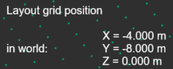
When hovering the mouse over the grid, its position is shown in the 3D Headup display. The display is automatically activated with the grid.
|
|
|
|
Process simulation objects

|
|
With the Show the process simulation objects button these objects are visualized or hidden .
|
|
|
|
|
|
Process geometry

|
|
With the Show the process geometry button the process geometry elements are displayed or hidden.
|
|
|
|
|
|
|
|
Render the process geometry on top
|
|
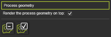
The option is a possibility to always show the process geometry elements on top of any geometry in any camera view direction, regardless if they would have been covered by any other geometry in front of the camera view.
|
|
|
|
|
|
And furthermore there is the option to show only the programmed or only the non-programmed process geometry by pressing on of the two buttons.
|
|

|
|
Manufacturing operations

|
|
With the Show the operation button the operation that is created on a process geometry is visualized or hidden .
|
|
|
|
|
|
Material flow objects

|
|
With the Show the material flow objects button the material flow source and sink objects are visualized or hidden. This visualization state can be set individually for these two objects.
|
|

|
|
|
|
|
|