Purpose
|
|
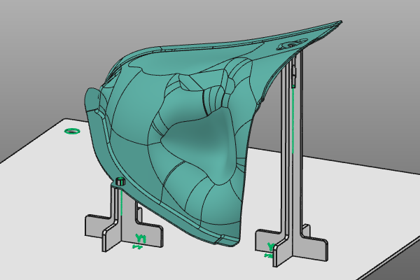
Workpieces may have some reference, like datum holes that are used for example for measuring or calibration of that part, or simply for fixation or storage. This page shows an example to design the fixture with use of that information to position and fixate the workpiece. The steps shown here will only focus on that part of the fixture design.
|
|

|
Load the project Fixture_Training_FixationPin.cendoc from the folder of this tutorial library.
|
|
|
|
Steps
|
|
1
|
Positioning the workpiece
|
|
1.1
|

|
With the Picking and Alignment functions the manipulator will be placed in the center of the datum hole. It defines the orientation of the workpiece in the fixture..

|
1.2
|

|
To focus on the topic of this tutorial page, only the fixture base plate will be created here.
In the Fixture default parameters, the number of support plates will be set to null. Then drag the manipulator below the workpiece and run the Create a fixture command the build the base plate.

|
|
|
|
|
2.1
|

|
Place the manipulator at the center of the datum hole. At its center, start the command Add support plate with given length. Set the value to 25mm and click to execute it. Two support plates are created.

|
2.2
|

|
The datum hole will now be used to fixate the workpiece.
At the intersection of the plates a green marker is displayed. Open the pie menu on this marker to set which type of plate intersection has to be created. Select the type Pin and see the result.

|
2.3
|

|
The pin may not have the correct size.
Change to the Measure operation mode. Pick the cylinder shape of the hole and execute the Measure object command. Its radius is being displayed. Then change back to the Normal operation mode.

|
2.4
|

|
Edit the pin diameter to match with the hole size. Have a look at the result.

|
|
|
|
|
3.1
|

|
Place the manipulator at the center of the other datum hole. At its center, start the command Add support plate with given length. Set the value to 15mm and click to execute it. Two new support plates are created.

|
3.2
|

|
The datum hole will be used to fixate the workpiece. But here a calibration pin will be placed to fixate the workpiece at its position.
Open the pie menu on the intersection marker and set the type of plate intersection to Pin hole. See the result.

|
|
|